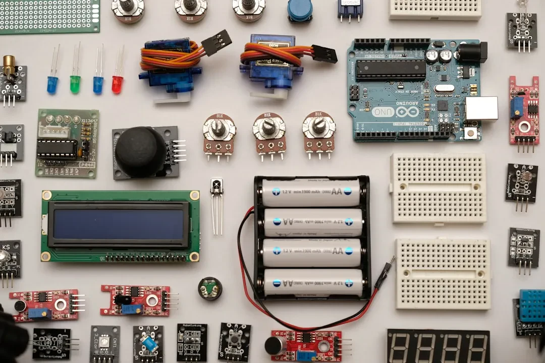
You have an IoT idea: a soil moisture sensor triggering an irrigation pump, or a DIY smart thermostat. But when you open the Arduino IDE, you feel lost among pins, sketches, and breadboards. The real issue isn't electronics — it's the lack of a clear mental map. At Meteora Web, we work daily with tech stacks ranging from pure code to embedded hardware. This guide cuts straight to the point: how to connect a breadboard, a sensor, an actuator, and make them talk to an Arduino microcontroller with real code and working examples.
Why Arduino and Not Another Microcontroller
Arduino is the right choice when you need a mature ecosystem, a huge community, and a board you can program via USB. A genuine board costs around €20-25, clones as low as €5, and it has everything for prototyping. We use it for quick tests with clients who want to validate an IoT idea before moving to industrial solutions (ESP32, STM32). Because a working prototype is worth more than a hundred slides.
Our Approach: From Breadboard to Revenue
We come from accounting: when we build an embedded system, we immediately calculate cost per unit, margin, and development time. A DHT22 sensor costs €3, a relay €2, an ESP32 €10. If the client wants 1,000 units, we already know the BOM is around €15 per unit. This lets us recommend the right board: for a pilot project, Arduino Uno is fine. For production, an ESP32 with integrated WiFi and lower cost is better.
Installing and Configuring the Arduino IDE
The official IDE (downloadable from arduino.cc) is simple and effective. We use it for quick sketches. For complex projects we switch to PlatformIO on VS Code (library management, serial debugging, multi-platform compilation). But to start, the IDE works perfectly.
First Connection: The Default Blink
Connect your board via USB, open the IDE, select your board (Tools > Board > Arduino Uno) and the correct COM port. Upload the 'Blink' example (File > Examples > 01.Basics > Blink). If the built-in LED blinks, you're in. If it doesn't, check drivers and port — common mistake.
// Basic Blink
void setup() {
  pinMode(LED_BUILTIN, OUTPUT);
}

void loop() {
  digitalWrite(LED_BUILTIN, HIGH);
  delay(1000);
  digitalWrite(LED_BUILTIN, LOW);
  delay(1000);
}
Essential Breadboard Circuits
A breadboard lets you connect components without soldering. Understanding the internal rails is the first step. Horizontal rails carry power (positive and negative). Vertical groups are connected rows. We often see beginners shorting everything because they don't know holes on the same row are connected. Golden rule: use different wire colors — red for VCC, black for GND, others for signals.
Basic Circuit: External LED with Resistor
Connect an LED to digital pin 13 via a 220Ω resistor (cathode to GND). The sketch is the same as Blink but change the pin to #define LED_PIN 13. Why the resistor? Without it, you burn the LED. Every component has an economic and technical cost: wrong resistor means wasted money and parts.
#define LED_PIN 13

void setup() {
  pinMode(LED_PIN, OUTPUT);
}

void loop() {
  digitalWrite(LED_PIN, HIGH);
  delay(500);
  digitalWrite(LED_PIN, LOW);
  delay(500);
}
Reading Sensors: Digital and Analog
Sensors divide into two families: digital (on/off, or with protocols like I2C/SPI) and analog (continuous value read via ADC). We always start with a simple sensor to test the circuit, then add complexity.
Digital Sensor: Push Button with Pull-Down
Connect a button to pin 2 with a 10kΩ pull-down resistor to GND. When pressed, the pin goes to 5V. When released, it stays at 0V. Code:
const int buttonPin = 2;
const int ledPin = 13;
int buttonState = 0;

void setup() {
  pinMode(buttonPin, INPUT);
  pinMode(ledPin, OUTPUT);
  Serial.begin(9600);
}

void loop() {
  buttonState = digitalRead(buttonPin);
  if (buttonState == HIGH) {
    digitalWrite(ledPin, HIGH);
    Serial.println("Button pressed");
  } else {
    digitalWrite(ledPin, LOW);
  }
}
Analog Sensor: Potentiometer
Connect a 10kΩ potentiometer: one leg to 5V, another to GND, the wiper to pin A0. Read the value with analogRead() (0-1023). Use it to control an LED brightness via PWM.
int potPin = A0;
int ledPin = 9;
int val = 0;

void setup() {
  pinMode(ledPin, OUTPUT);
  Serial.begin(9600);
}

void loop() {
  val = analogRead(potPin);
  int brightness = map(val, 0, 1023, 0, 255);
  analogWrite(ledPin, brightness);
  Serial.print("Value: ");
  Serial.println(val);
  delay(50);
}
Actuators: From Motors to Relays
An actuator turns an electrical signal into motion or action. Common ones: LEDs, servos, DC motors, relays. Watch out for current: a DC motor draws more than an Arduino pin can supply (max 40mA per pin). Use a transistor or driver (L298N, ULN2003). Never power a motor directly from an Arduino pin: you risk frying the board.
Servo Motor SG90: Position Control
The servo has three wires: VCC (red, 5V), GND (brown), and signal (orange). Connect signal to a PWM pin (9 or 10). Use the Servo.h library to command the angle (0-180°).
#include <Servo.h>
Servo myservo;
int potPin = A0;

void setup() {
  myservo.attach(9);
}

void loop() {
  int val = analogRead(potPin);
  int angle = map(val, 0, 1023, 0, 180);
  myservo.write(angle);
  delay(15);
}
Relay: Switching 220V Safely
A relay module has a control input (IN1) connected to a digital pin. Setting it HIGH activates the relay and closes the external circuit (lamp, pump). Always isolate the low-voltage side from the 220V side: use an optoisolated relay. We once automated fitting-room lights with Arduino + relay for a clothing store: it cost less than a commercial system and worked exactly the same.
#define RELAY_PIN 7

void setup() {
  pinMode(RELAY_PIN, OUTPUT);
  digitalWrite(RELAY_PIN, LOW);  // relay off
}

void loop() {
  // Turn on for 5 seconds
  digitalWrite(RELAY_PIN, HIGH);
  delay(5000);
  digitalWrite(RELAY_PIN, LOW);
  delay(5000);
}
From Prototype to Product: What Changes
A breadboard prototype is the first step. But if you want to sell the device, you need to: design a PCB, choose a cheaper microcontroller (e.g., bare ATmega328P instead of an Arduino board), and think about power supplies. We help clients make this leap: owning your hardware stack (schematic + PCB + firmware) beats renting pre-made modules with lifetime subscriptions. A client producing 500 units per year saves 40% by switching from Arduino Nano to a custom PCB.
Security in Embedded IoT
We see it often: sensors exposed on local networks with no encryption, credentials hardcoded in firmware, no overflow protection. If your device is connected to the internet, it's a target. Don't leave serial ports open in production, use TLS for communications, and update firmware OTA only with authentication. When we faced a broken SSL auto-renewal on a server, we automated it — same approach for IoT nodes: each node must have a certificate and a rotation mechanism.
In Summary — What to Do Now
- Install the Arduino IDE and upload the default Blink to verify your board.
- Set up a breadboard with an LED and resistor: master reading a digital pin.
- Read an analog sensor (potentiometer or LDR with resistor) and print values to the Serial Monitor.
- Control an actuator: try a servo or relay using the code above.
- Combine everything: a sensor that triggers a relay when a threshold is exceeded (e.g., temperature > 30°C turns on a fan).
- Document component costs: you'll need them to decide whether to move to production.
A well-built IoT project starts with these building blocks. If you need to go from prototype to product, we at Meteora Web can help you calculate numbers and choose the right stack. Because a sensor alone is worth nothing, but an integrated system that generates data and actions is worth everything.
Sponsored Protocol